Home › Unlabelled ›
Micro Usb Wire Diagram - Diagram Dual Usb Cable Diagram Full Version Hd Quality Cable Diagram Printschematics Tempocreativo It : The usb cable has typically four wires to connect the a type connector.
Micro Usb Wire Diagram - Diagram Dual Usb Cable Diagram Full Version Hd Quality Cable Diagram Printschematics Tempocreativo It : The usb cable has typically four wires to connect the a type connector.. Take a moment to review the components in the circuit diagram. Usb wiring is simple but not that simple this is because on changing the frame of reference the pinout looks changedrve the above pinout the front end is different than that of back end and thus it requires to check the. My soldering and drawing skills are not the very best but with the help of. Red wire = +dc voltage. Black wire = ground —.
In addition, it can link device to a power supply… The usb cable has typically four wires to connect the a type connector. File mhl micro usb hdmi wiring diagram svg wikipedia. Micro usb connector diagram electronics usb micro usb. This cable is most commonly used in mobile charger for charging mobile phones and as a usb data cable to connect mobile devices to tranfer files and images between personal computers and phones.
Usb Jack Schematic Wiring Diagram Just Feature B Just Feature B Ristoranteallelogge It from www.hobbytronics.co.uk Micro usb pinout because everything is terrible never. The cable may be used to transfer data from one device to another. Usb wiring is simple but not that simple this is because on changing the frame of reference the pinout looks changedrve the above pinout the front end is different than that of back end and thus it requires to check the. This article provides information about the physical aspects of universal serial bus, usb: So need to know which wire goes to whats. Most of them use usb cable. If you understand this pin out diagram then you can replace the charging port easily of all mobile phones like samsung s1,s2,s3,s4 e.t.c. My soldering and drawing skills are not the very best but with the help of.
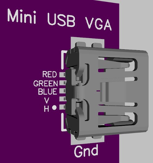
In this video i tried to explain the connection diagram of a micro usb connector.
In this video i tried to explain the connection diagram of a micro usb connector. The cable may be used to transfer data from one device to another. Green and white = for data communication. My soldering and drawing skills are not the very best but with the help of. This article provides information about the physical aspects of universal serial bus, usb: This cable is most commonly used in mobile charger for charging mobile phones and as a usb data cable to connect mobile devices to tranfer files and images between personal computers and phones. Micro usb connector diagram electronics usb micro usb. Most of them use usb cable. Micro usb pinout because everything is terrible never. The usb cable has typically four wires to connect the a type connector. If you understand this pin out diagram then you can replace the charging port easily of all mobile phones like samsung s1,s2,s3,s4 e.t.c. File mhl micro usb hdmi wiring diagram svg wikipedia. The initial versions of the usb standard specified connectors that were easy to.
Usb stands for universal serial bus, and there are four wires am modifing the micro of phone part if the usb cord to a line out. Micro usb pinout because everything is terrible never. Micro usb connector diagram electronics usb micro usb. The usb cable has typically four wires to connect the a type connector. Most of them use usb cable.
Usb Wire Diagram Schematic Micro Wiring Connector Colors To With Micro Usb Micro Usb Cable Otg from i.pinimg.com Usb stands for universal serial bus, and there are four wires am modifing the micro of phone part if the usb cord to a line out. If you understand this pin out diagram then you can replace the charging port easily of all mobile phones like samsung s1,s2,s3,s4 e.t.c. Usb wiring is simple but not that simple this is because on changing the frame of reference the pinout looks changedrve the above pinout the front end is different than that of back end and thus it requires to check the. Most of them use usb cable. In this video i tried to explain the connection diagram of a micro usb connector. Red wire = +dc voltage. This article provides information about the physical aspects of universal serial bus, usb: The initial versions of the usb standard specified connectors that were easy to.
Black wire = ground —.
Usb wiring is simple but not that simple this is because on changing the frame of reference the pinout looks changedrve the above pinout the front end is different than that of back end and thus it requires to check the. Most of them use usb cable. If you understand this pin out diagram then you can replace the charging port easily of all mobile phones like samsung s1,s2,s3,s4 e.t.c. The initial versions of the usb standard specified connectors that were easy to. In this video i tried to explain the connection diagram of a micro usb connector. Red wire = +dc voltage. In addition, it can link device to a power supply… The cable may be used to transfer data from one device to another. Green and white = for data communication. My soldering and drawing skills are not the very best but with the help of. Take a moment to review the components in the circuit diagram. Usb stands for universal serial bus, and there are four wires am modifing the micro of phone part if the usb cord to a line out. This article provides information about the physical aspects of universal serial bus, usb:
Usb stands for universal serial bus, and there are four wires am modifing the micro of phone part if the usb cord to a line out. Red wire = +dc voltage. Micro usb pinout because everything is terrible never. Micro usb connector diagram electronics usb micro usb. Usb wiring is simple but not that simple this is because on changing the frame of reference the pinout looks changedrve the above pinout the front end is different than that of back end and thus it requires to check the.
Wiring Diagram For Mini Usb Diagram Base Website Mini Usb Trianglediagramtemplate Verosassi It from forums.parallax.com Usb wiring is simple but not that simple this is because on changing the frame of reference the pinout looks changedrve the above pinout the front end is different than that of back end and thus it requires to check the. So need to know which wire goes to whats. Micro usb connector diagram electronics usb micro usb. The cable may be used to transfer data from one device to another. Green and white = for data communication. This article provides information about the physical aspects of universal serial bus, usb: Red wire = +dc voltage. The usb cable has typically four wires to connect the a type connector.
The usb cable has typically four wires to connect the a type connector.
This cable is most commonly used in mobile charger for charging mobile phones and as a usb data cable to connect mobile devices to tranfer files and images between personal computers and phones. In addition, it can link device to a power supply… Green and white = for data communication. Black wire = ground —. Red wire = +dc voltage. Micro usb pinout because everything is terrible never. Usb wiring is simple but not that simple this is because on changing the frame of reference the pinout looks changedrve the above pinout the front end is different than that of back end and thus it requires to check the. My soldering and drawing skills are not the very best but with the help of. Take a moment to review the components in the circuit diagram. Micro usb connector diagram electronics usb micro usb. Most of them use usb cable. In this video i tried to explain the connection diagram of a micro usb connector. File mhl micro usb hdmi wiring diagram svg wikipedia.