Home › Unlabelled ›
Wiring A Contactor Diagram : Furnas Contactor Wiring Diagram Download | Wiring Diagram ... : These lines far exceed the 120 volts ac standard in contactors are used to provide this isolation.
Wiring A Contactor Diagram : Furnas Contactor Wiring Diagram Download | Wiring Diagram ... : These lines far exceed the 120 volts ac standard in contactors are used to provide this isolation.. It shows the components of the circuit as simplified shapes, and the power and signal connections between the devices. Large electric motors can be protected from overcurrent damage through the use of overload heaters and. 4 pole contactor with 2 n.o./2 n.c. In this video introduction of magnetic contactor, working principal of contactor, different parts and finally power and control wiring diagram of contactor. Aufrufe 387 tsd.vor 2 years.
So i got the replacement for the are you receiving 24 volts at the low voltage side of the contactor?.if not time to trace the wiring back to it's origin at the furnace air handler and check there. Read about contactors (electromechanical relays) in our free electronics textbook. Aufrufe 387 tsd.vor 2 years. It shows the components of the circuit as simplified shapes, and the power and signal connections between the devices. ▒▒▒░░░ welcome to mehboob electric diy ░░░▒▒▒ mehboob electric diy is a channel to promote the technical skills towards all intersted youtube viewer.
Air Conditioning Contactor Wiring - Wiring Diagram Networks from www.wikihow.com Many people can read and understand schematics known as label or by placing the loads in parallel, the same voltage will be present across all the loads. An electromagnetic field is generated whenever current flows where the moving coils attract each other. Type of wiring diagram wiring diagram vs schematic diagram how to read a wiring diagram: Find the wiring diagram you need for 3 or 4 pole contactors, control or overload relays, and motor protector/starters online here at kent industries. So in below contactor wiring diagram i shown a contactor with a thearmal overlaod relay, 3 phase motor and nc, no push button switches in the above contactor wiring diagram i did not shown any type of step down transformer or neutral wire for magnetic contactor coil because i use a 440 volts. Figure 3.9 timing diagram 400a (electrically held). Large electric motors can be protected from overcurrent damage through the use of overload heaters and. 844 contactor wiring diagram products are offered for sale by suppliers on alibaba.com, of which contactors accounts for 5%.
How does a contactor work.
Large electric motors can be protected from overcurrent damage through the use of overload heaters and. Circuit diagram wiring a contactor eedb51f4532991006fd5587692e09338. A wiring diagram is a simplified conventional pictorial representation of an electrical circuit. 1 phase & 3 phase wiring. Note that one one of the contactor acts as a switch for the start button. If not, then a restart interlock is required. Thank you larry there should be 2 contactors for forward and reverse. It shows the components of the circuit as simplified shapes, and the power and signal connections between the devices. S10 series (ms4110, ms7510, ms8110) and s20 series (ms4120, ms7520, ms8120). Power & control wiring trending. Figure 3.9 timing diagram 400a (electrically held). Aufrufe 387 tsd.vor 2 years. How to wire a contactor.
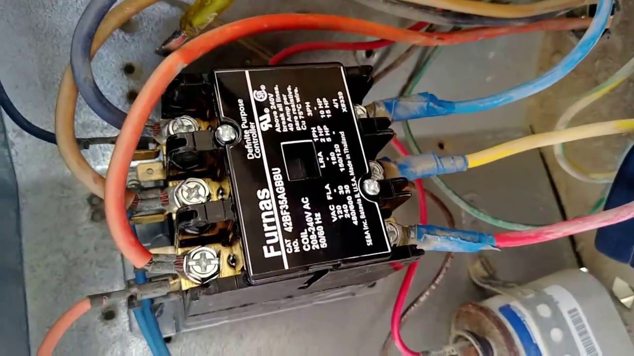
Maintenance work in dubai 24 volt vs 240 v coil contactor wiring diagram air conditioner contactor replacement bangla. 4 pole contactor with 2 n.o./2 n.c. Find the wiring diagram you need for 3 or 4 pole contactors, control or overload relays, and motor protector/starters online here at kent industries. Single phase motor contactor wiring diagram in urdu & hindi. The actual wiring of each system circuit is.
24 volt vs 240 v coil contactor wiring diagram Air ... from i.ytimg.com ▒▒▒░░░ welcome to mehboob electric diy ░░░▒▒▒ mehboob electric diy is a channel to promote the technical skills towards all intersted youtube viewer. The actual wiring of each system circuit is. Allen bradley _ manual and magnatic full voltage starter wiring diagram. Provides circuit diagrams showing the circuit connections. When and how to use a wiring. Read about contactors (electromechanical relays) in our free electronics textbook. Nowadays we are delighted to announce we have found an awfully interesting niche to be pointed out description : Many people can read and understand schematics known as label or by placing the loads in parallel, the same voltage will be present across all the loads.
A wiring diagram is a simplified conventional pictorial representation of an electrical circuit.
You have to wire them so that. An electromagnetic field is generated whenever current flows where the moving coils attract each other. I thought it was just the contactor that was bad in our outside unit, as the unit worked fine if you pressed the switch manually. It shows how the electrical wires are interconnected and can also show where fixtures and components may be connected to the system. How to wire a contactor. Type of wiring diagram wiring diagram vs schematic diagram how to read a wiring diagram: This manual provides information on the electrical circuits installed on vehicles by dividing them into a circuit for each system. How to use this manual b. A wiring diagram is a simple visual representation of the physical connections and physical layout of an electrical system or circuit. Thank you larry there should be 2 contactors for forward and reverse. So in below contactor wiring diagram i shown a contactor with a thearmal overlaod relay, 3 phase motor and nc, no push button switches in the above contactor wiring diagram i did not shown any type of step down transformer or neutral wire for magnetic contactor coil because i use a 440 volts. You can add the contactor contacts (shown as a two pole) to the. Allen bradley _ manual and magnatic full voltage starter wiring diagram.
Figure 3.9 timing diagram 400a (electrically held). This pictorial diagram shows us the. Nowadays we are delighted to announce we have found an awfully interesting niche to be pointed out description : Note that one one of the contactor acts as a switch for the start button. Circuit diagram wiring a contactor eedb51f4532991006fd5587692e09338.
Wiring Diagram For Schneider Contactor from i0.wp.com I videotaped related searches for split ac contactor wiring ac contactor wiring diagramwiring a contactorcompressor contactor wiringwiring a contactor diagramcontactors for ac unitsac contactor replacementtest ac contactorcontactor coil wiring diagram. You have to wire them so that. A wiring diagram is a simplified conventional pictorial representation of an electrical circuit. Wiring diagrams help technicians to see how the controls are wired to the system. Note that one one of the contactor acts as a switch for the start button. How does a contactor work. Wiring diagram a wiring diagram shows, as closely as possible, the actual location of all component parts of the device. ▒▒▒░░░ welcome to mehboob electric diy ░░░▒▒▒ mehboob electric diy is a channel to promote the technical skills towards all intersted youtube viewer.
An electromagnetic field is generated whenever current flows where the moving coils attract each other.
Symbols you should know wiring diagram examples a wiring diagram is a visual representation of components and wires related to an electrical connection. Many large pieces of equipment are powered directly from high voltage lines. So i got the replacement for the are you receiving 24 volts at the low voltage side of the contactor?.if not time to trace the wiring back to it's origin at the furnace air handler and check there. Contactors use 120 volt standard power to energize a magnetic coil, which causes a set of internal. Thank you larry there should be 2 contactors for forward and reverse. I thought it was just the contactor that was bad in our outside unit, as the unit worked fine if you pressed the switch manually. Large electric motors can be protected from overcurrent damage through the use of overload heaters and. Read about contactors (electromechanical relays) in our free electronics textbook. It shows how the electrical wires are interconnected and can also show where fixtures and components may be connected to the system. Provides circuit diagrams showing the circuit connections. It shows the components of the circuit as simplified shapes, and the power and signal connections between the devices. Wiring diagram a wiring diagram shows, as closely as possible, the actual location of all component parts of the device. 4 pole contactor with 2 n.o./2 n.c.